
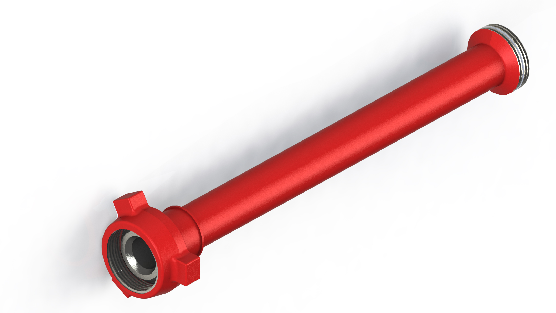
TREATING IRON/ CROSSOVER/ BLAST JOINT
ACT’S one piece Treating Iron comprises an integral ACT’S wing union end connection which eliminates, welds and threads.Available in lengths up to 20 feet. The materials are carbon steel and alloy steel and are light weight.
Available in lengths up to 20 feet. The materials are carbon steel and alloy steel and are light weight. This integral treating iron is capable of handling a variety of fluids at cold working pressure of 15000 psi. ACT’S treating irons are also available for sour service up to a CWP of 10,000 PSI & in other lengths if required.
TREATING IRONS
CROSSOVERS
These are suitable for High Pressure Discharge Lines, Temporary Flow Lines, Auxiliary Flow Lines, Well Testing Lines, Water Lines, Choke and Kill Lines and Abrasive Applications.Since there are no welds and threads, ACT’S treating irons provide an uniform bore of greater flow capacity and improved flow characteristics. ACT’S design allows for uniform heat treating of the entire joint for better structural qualities. Nut can be detached for easy disassembly if replacement becomes necessary. For this only a circlip has to be removed.
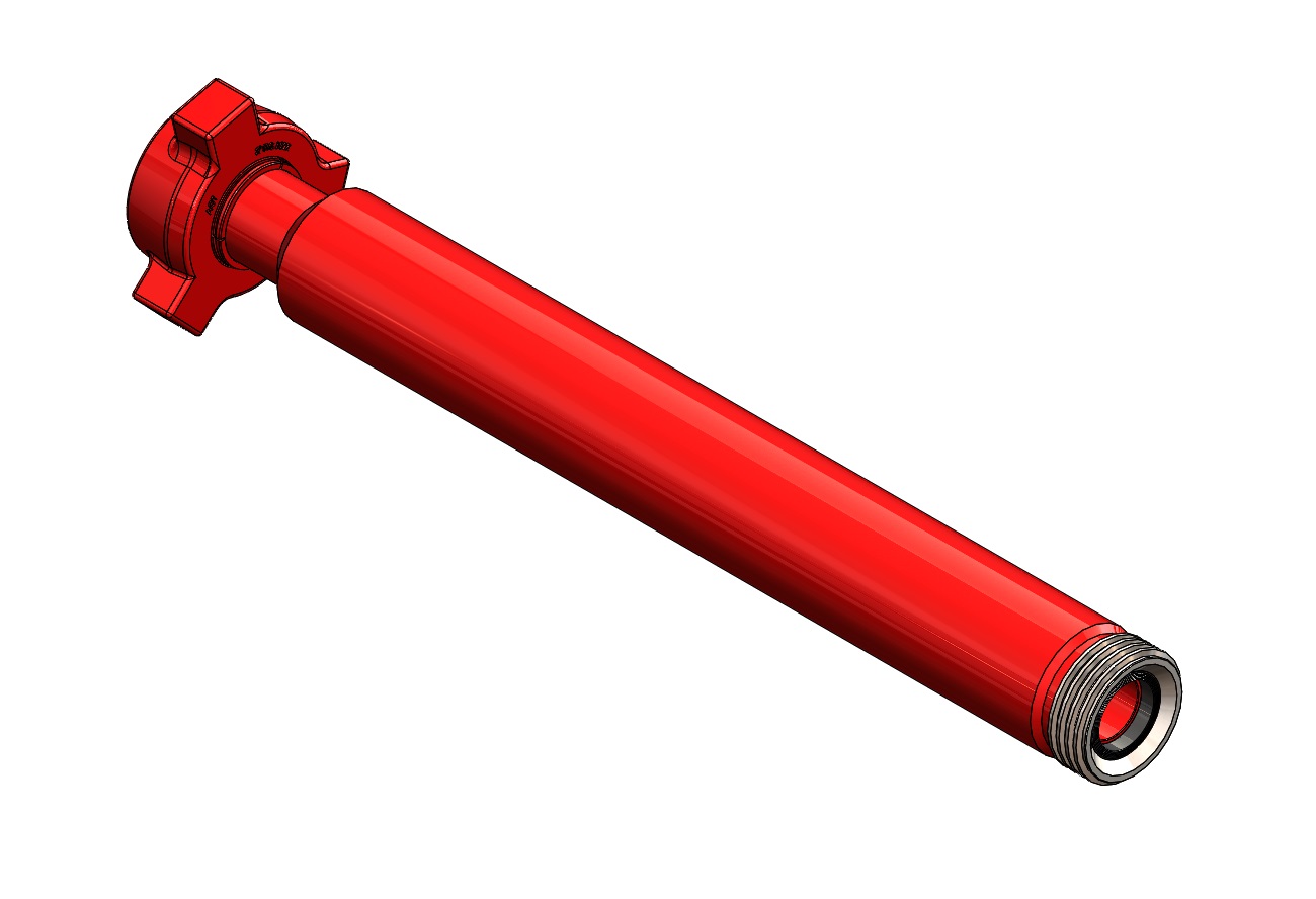
NPST Pup joints are made of high quality seamless pipeline with male & female detachable hammer union. NPST has uniform bore for greater flow capacity. NPST pup joints are available in 2″ to 4″ sizes, length for pup joint range from 1 feet to 20 feet at 15000 psi. Pup joint with Non- pressure seal thread union (NPST) are especially engineered for high pressure, abrasive services where welded connections are not desired. The design provides a strong, permanent end connection without butt welding. An epoxy thread-locking compound secures the connection.
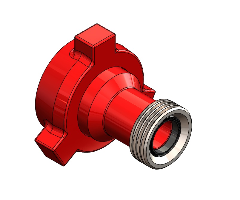
BLAST JOINT
Pressure seal pipe threads (PST) are not recommended for pulsating service above 10000 psi or where side loading or erosion are suspected. NPST threads or straight integral connection are better under these conditions. In order to achieve the recommended NSCWP*, power tight make up is required on threaded connections. connecting pipes are Line Pipe “V” Threads.
| DIMENSIONAL REFERENCE CHART | |||||||||||||||||
|---|---|---|---|---|---|---|---|---|---|---|---|---|---|---|---|---|---|
| SIZE (IN) | 1” | 1- 1 /2” | 2” | 2- 1 /2” | 3” | 4” | 5" | 6" | 12" | ||||||||
| FIGURE | 602 | 1502 | 602 | 1502 | 602 | 1502 | 602 | 1502 | 602 | 1502 | 602 | 1502 | 1002 | 1502 | 1002 | 1502 | 900 |
| WORKING PRESSURE (PSI) | 6000 | 15000 | 6000 | 15000 | 6000 | 15000 | 6000 | 15000 | 6000 | 15000 | 6000 | 15000 | 10000 | 15000 | 10000 | 15000 | 2500 |
| TEST PRESSURE (PSI) | 9000 | 22500 | 9000 | 22500 | 9000 | 22500 | 9000 | 22500 | 9000 | 22500 | 9000 | 22500 | 15000 | 22500 | 15000 | 22500 | 3750 |
| WALL (T) MM | 6.35 | 9.09 | 7.14 | 10.16 | 8.74 | 13 | 7.14 | 14.02 | 7.62 | 15.24 | 13.49 | 17.11 | 15.87 | 19.05 | 18.26 | 21.94 | 14.15 |
| INCH | 0.250 | 0.358 | 0.281 | 0.400 | 0.344 | 0.511 | 0.281 | 0.552 | 0.300 | 0.600 | 0.531 | 0.674 | 0.625 | 0.750 | 0.719 | 0.864 | 0.557 |
| APPROX WT. PIPE: LBSF /FT KGF /M H UNION; LBSF KGF | 2.84
4.24 3.30 1.50 |
3.66
5.45 8.50 3.80 |
4.86
7.25 9.70 4.40 |
6.41
9.56 12.80 5.70 |
6.28
9.36 12.12 5.50 |
9.03
13.44 20.30 9.20 |
8.0
14.92 15.87 7.20 |
11.81
20.39 23.00 10.30 |
10.25
15.27 20.94 9.50 |
18.58
27.68 29.50 13.30 |
22.51
33.54 30.66 14.00 |
28.65
42.65 76.50 34.40 |
32.96
49.04 56.00 25.40 |
38.55
57.36 99.00 44.90 |
45.35
67.48 79.80 36.19 |
53.16
79.10 155.00 70.30 |
49.00
72.92 94.13 42.69 |
| LENGTH L (FEET) | 2’ , 3’ , 4’ , 5’ , 6’ , 7’ , 8’, 9’ , 10’ , 12’, 15', 20' | ||||||||||||||||